

Why NEMA Locking Plugs Matter for North American Rack PDUs
NEMA locking plugs are the standard for commercial and industrial AC power connections in North America because the mechanical twist-lock connection resists vibration and accidental disconnection in a way that straight-blade connections cannot. The twist-lock works because the plug blades are curved rather than straight, and the receptacle slots have matching curves plus a spiral track. When the plug is inserted and rotated clockwise, the blades travel along the spiral track until they reach a locked position. Reverse rotation releases the lock and allows the plug to be withdrawn. The result is a connection that will not pull out under vibration, cable strain, or accidental tug on the power cord.
For rack PDU applications, the locking mechanism is required by code for any installation where the receptacle serves equipment that is moved infrequently but could be subject to cable strain or vibration. The most common scenario is a server rack in a data center where the power cord is routed through a cable management arm and bears the weight of the cable management pathway. A straight-blade connection in this configuration will eventually work loose because the cable weight pulls the plug at an angle. A locking connection holds until deliberately released by rotating the plug counter-clockwise.
The NEMA WD 6 standard governs the dimensional specifications for locking plugs and receptacles, including blade angles, diameters, and the polarity arrangements that prevent mismatched connections. The standard is maintained by the National Electrical Manufacturers Association and is the reference document for every locking configuration in service. UL 498 is the safety standard for attachment plugs, receptacles, and cord connectors, and works in tandem with NEMA WD 6 to define both the mechanical and electrical requirements.
Within the NEMA locking family, the most common single-phase configurations are L5-30 (125V, 30A, 2P3W grounding) and L6-30 (250V, 30A, 2P3W grounding). The two share 30A current and 2P3W architecture but differ in voltage and blade angular position; the latter is what prevents cross-mating.
NEMA L5-30 Specifications: 125V / 30A / 2P3W Grounding
NEMA L5-30 is a 125V, 30A, 2-pole 3-wire grounding locking configuration. The two poles are the two hot conductors, the third wire is the equipment grounding conductor, and there is no neutral. The configuration is designed for 120V single-phase service, which is the standard nominal voltage for North American residential and small commercial circuits, and for many North American data center branch circuits that feed lower-power rack PDU loads.
The absence of a neutral is the defining feature of L5-30 and distinguishes it from L14-30 (which has a neutral) and L21-30 (which has three phases plus a neutral). Most North American 120V single-phase rack PDUs use L5-30P plugs. The 30A rating is the maximum continuous current; for continuous loads, the conductor and receptacle must be rated at 125 percent of the continuous load current per NEC Article 100.
NEMA L6-30 Specifications: 250V / 30A / 2P3W Grounding
NEMA L6-30 is a 250V, 30A, 2-pole 3-wire grounding locking configuration. The two poles are again the two hot conductors, the third wire is the equipment grounding conductor, and there is no neutral. The configuration is designed for 208V or 240V single-phase service, which is the standard nominal voltage for North American data center branch circuits that feed higher-power rack PDU loads.
The 250V rating is the nominal voltage rating that the configuration is designed and tested for. The actual service voltage in most North American data center installations is 208V (not 240V), because the data center distribution transformer is typically 480V delta primary to 208Y/120V secondary. The 250V rating provides 42V of headroom above the 208V service, which is sufficient to handle transient overvoltages on the data center electrical distribution.
Like L5-30, L6-30 has no neutral and uses 2P3W architecture. For 208V service, the two hot conductors are the two phases of the 208Y/120V secondary not paired with the neutral. The L6-30 grounding pin is at 300-degree clockwise rotation versus 270 degrees for L5-30, which prevents cross-mating. L6-30 is the de facto standard for 208V single-phase rack PDU circuits; the 208V / 30A combination provides approximately 6.2 kVA of capacity for a rack hosting 4 to 6 kW of IT load.
Side-by-Side Comparison: L5-30 vs L6-30 Specifications
The side-by-side comparison below shows the key dimensions and ratings that differentiate the two configurations. The table is the working reference for the procurement and electrical design teams who must specify the right plug for each rack PDU application.
specific
| Parameter | L5-30 | L6-30 | Differentiator |
|---|---|---|---|
| Voltage rating | 125V AC | 250V AC | Service voltage match |
| Current rating | 30A | 30A | Same |
| Configuration | 2P3W grounding | 2P3W grounding | Same |
| Neutral conductor | None | None | Same |
| Grounding conductor | Required | Required | Same |
| Blade angular position (X to G) | 270 deg | 300 deg | Cross-mating interlock |
| Frequency | 60 Hz | 60 Hz | Same |
| UL standard | UL 498 | UL 498 | Same |
| NEMA standard | WD 6 | WD 6 | Same |
| Minimum conductor | 10 AWG Cu | 10 AWG Cu | Same |
| Typical application | 120V rack PDU | 208V rack PDU | Voltage-dependent |
| Nominal service | 120V single-phase | 208V or 240V single-phase |
The two configurations are voltage-specific. Choosing the wrong configuration means a mismatch at the receptacle or busway, requiring a replacement PDU or receptacle. The right configuration is determined by the service voltage at the rack, not by the PDU rating itself.

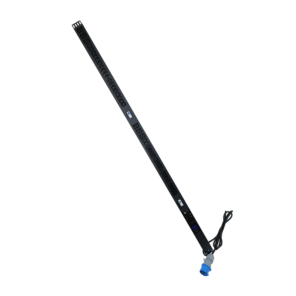
Mechanical Locking Mechanism: How the Curved Blade Twist-Lock Works
The mechanical locking mechanism is the defining feature of every NEMA locking configuration. The mechanism is what distinguishes a locking plug from a straight-blade plug and is the reason the locking configurations are required by code for commercial and industrial applications. Understanding the mechanism is the foundation for understanding why the locking family is the standard for rack PDU installations.
The plug has three curved blades. Each blade is curved in the same rotational direction (clockwise when viewed from the front of the plug). The receptacle has three matching slots that are also curved. When the plug is inserted, the blades enter the slots in the unlocked position. The plug is then rotated clockwise by approximately 30 to 45 degrees, which causes the blades to travel along the curved track in the receptacle. The travel brings the blades to a locked position where a detent or other mechanical feature holds the plug in place. Reverse rotation releases the lock and allows the plug to be withdrawn.
The locking mechanism resists three failure modes that straight-blade connections suffer. First, it resists axial pull-out, because the blades cannot travel backward along the spiral track without first being rotated counter-clockwise. Second, it resists lateral strain, because the curved blades and curved slots engage in a way that distributes the strain across the contact surface rather than concentrating it at the insertion point. Third, it resists vibration loosening, because the detent holds the plug in the locked position against vibration that would otherwise work a straight-blade plug loose.
For rack PDU applications, the locking mechanism has two practical implications. First, the power cord can be routed through a cable management arm without fear that the cord weight will work the plug loose. Second, the locked connection is more reliable for high-amperage circuits where any intermittent contact at the blade-to-slot interface would generate heat and could become a fire hazard. Both implications are why data center electrical designers specify locking configurations for rack PDU service.
The locking mechanism has one practical drawback. The plug cannot be quickly disconnected in an emergency, because the rotation-and-withdrawal sequence takes more time than a straight-blade pull. For rack PDU applications this is not a problem, because the PDU is rarely disconnected under power. For emergency power-off scenarios, the EPO button at the rack or the upstream breaker trip is the standard shutdown path, not the PDU plug.
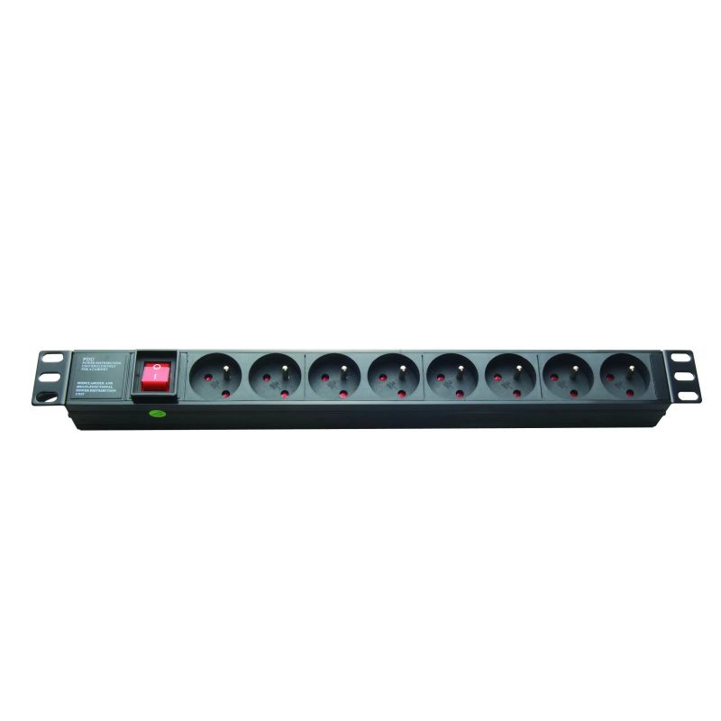
UL 498 and NEMA WD 6 Compliance: What Buyers Should Verify
UL 498 and NEMA WD 6 are the two standards that govern L5-30 and L6-30 plugs and receptacles. UL 498 is the safety standard; NEMA WD 6 is the dimensional standard. A plug or receptacle that is UL 498 listed and conforms to NEMA WD 6 will mechanically and electrically match every other plug and receptacle of the same configuration, regardless of the manufacturer. The two standards work in tandem and are the reference framework for any procurement specification.
UL 498 covers attachment plugs, receptacles, and cord connectors for general use. The standard includes the locking-blade configurations that are part of the NEMA WD 6 family. UL 498 testing includes dielectric voltage withstand, insulation resistance, temperature rise, blade pull-out force, and a range of mechanical endurance tests. A UL 498 listed plug has been tested by UL and is manufactured under UL’s follow-up service, which means UL audits the manufacturer’s production line on a regular basis to confirm continued compliance.
Buyers should verify the UL 498 listing by checking the UL Online Certifications Directory for the manufacturer’s file number and the catalog number of the plug or receptacle.
NEMA WD 6 is the dimensional standard that defines the blade angles, diameters, spacing, and polarity for every locking configuration. The standard is maintained by NEMA and is the reference document that manufacturers use to produce interchangeable products. NEMA WD 6 is the standard that makes the L5-30 plug from one manufacturer mechanically and electrically interchangeable with the L5-30 receptacle from another manufacturer.
The Newsunn product certification list documents the UL 498 file numbers for the L5-30P and L6-30P plug options available on the basic and metered PDU families. The certificate list is updated annually and includes the NEMA WD 6 conformity attestation per configuration. Buyers should request the certificate list with the per-configuration file number as part of the procurement documentation package.
Common Applications: When L5-30 vs L6-30 Is the Right Choice
The choice between L5-30 and L6-30 is determined by the service voltage at the rack PDU, not by the PDU rating itself. The service voltage at the rack is set by the data center electrical designer’s choice of distribution transformer and the rack’s position on the distribution panel. The procurement specification for the rack PDU must therefore specify the plug configuration that matches the service voltage, not a generic “30A locking plug.”
| Application | Service Voltage | Recommended Plug | Rationale |
|---|---|---|---|
| Small server room 120V service | 120V | L5-30P | Match the 120V service |
| Retail back-office IT 120V service | 120V | L5-30P | Match the 120V service |
| Data center 208V single-phase rack PDU | 208V | L6-30P | Standard for 208V service |
| Data center 240V single-phase rack PDU | 240V | L6-30P | Standard for 240V service |
| Higher-power rack (5-10 kVA) 208V | 208V | L6-30P | Match the 208V service |
| Lower-power rack (1-3 kVA) 120V | 120V | L5-30P | Match the 120V service |
| Residential or home office 120V | 120V | L5-30P | Match the 120V service |
The most common data center scenario is the 208V single-phase rack PDU, where L6-30P is the de facto standard. The combination of 208V service and 30A current provides approximately 6.2 kVA of capacity, which is the typical sizing for a rack hosting 4 to 6 kW of IT load. For higher-power racks (10 kW+), the configuration steps up to L6-50P or CS6365.
The 120V scenarios are less common in modern data center builds but persist in small server rooms, retail back-office IT installations, and residential-class installations. For these, L5-30P is the standard locking configuration.
Compatibility with IEC C13/C19 Outlets and Adapter Considerations
Most rack PDUs ship with NEMA L5-30P or L6-30P plugs on the input cord and IEC C13 or C19 outlets on the output side. The NEMA plug is the input-side connection to the floor box or busway; the IEC outlets are the output-side connections to the IT equipment. The two connection standards are independent and serve different roles in the rack PDU architecture.
IEC C13 is a 10A / 250V AC cold-condition connector, and IEC C19 is a 16A / 250V AC cold-condition connector. Both are rated for 250V, which means they can be used on either 120V or 208V service on the output side. The input-side NEMA plug determines the voltage of the service, but the output-side IEC outlets are voltage-agnostic. The combination is what makes a single rack PDU platform configurable for either 120V or 208V service by swapping the input cord.
The Newsunn basic and metered PDU families offer configurable input cords: L5-30P for 120V service or L6-30P for 208V / 240V service. The IEC C13 / C19 outlet complement is the same regardless. Adapters between NEMA and IEC exist but are not recommended for permanent rack PDU installations because they introduce a potential failure point in the power path.
Wire Gauge and Circuit Breaker Sizing for 30A Locking Circuits
The wire gauge and circuit breaker sizing for L5-30 and L6-30 circuits is governed by the National Electrical Code (NEC). Article 310.16 sets the ampacity table for conductors; Article 240.4 sets the overcurrent protection rules. The two articles work together to define the conductor size and the breaker size for a given receptacle configuration.
The minimum conductor for a 30A L5-30 or L6-30 circuit is 10 AWG copper, rated at 75°C, which provides 35A of ampacity per the NEC table. For a continuous load at exactly 30A, the conductor must be rated at 125 percent of the continuous load, which would be 37.5A, exceeding the 35A ampacity of 10 AWG. In practice, the continuous load on a rack PDU circuit is typically less than 24A (because the rack IT load is below the PDU rating), so 10 AWG is acceptable. For circuits where the continuous load approaches 30A, 8 AWG is the recommended conductor size.
The standard breaker size is 30A per NEC 240.4. The breaker must be listed for the voltage (120/240V AC for L5-30 circuits, 240V AC for L6-30 circuits) and must be HACR rated if the PDU includes a hermetic refrigerant motor load, which is uncommon for rack PDUs but possible for PDUs that include integral cooling. The breaker must be coordinated with the conductor ampacity, which means a 30A breaker on 10 AWG conductor and a 40A breaker on 8 AWG conductor are the two standard combinations.
For runs over 100 feet, upsizing to 8 AWG limits voltage drop below 3 percent (per NEC recommendation for branch circuits). The cost premium for 8 AWG over 10 AWG is typically 20 to 30 percent per foot.
Next Steps and Frequently Asked Questions
For procurement teams specifying rack PDUs for North American data center installations, the practical first move is to confirm the service voltage at the rack (120V or 208V) and to specify the input plug accordingly (L5-30P or L6-30P). The wire gauge and circuit breaker sizing follow from the receptacle choice per NEC 310.16 and 240.4. The Newsunn export team can align the input cord selection with the basic or metered PDU platform through the single-phase rack PDUs configuration tool, and the US NEMA rack power strip product line provides the platform reference for both L5-30 and L6-30 configurations.
What is the difference between NEMA L5-30 and L6-30?
NEMA L5-30 is a 125V, 30A, 2-pole 3-wire grounding locking plug and receptacle configuration, while NEMA L6-30 is a 250V, 30A, 2-pole 3-wire grounding configuration. The L5-30 has two hot blades (X, Y) plus a grounding pin; the L6-30 also has two hot blades (X, Y) plus a grounding pin but is rated for 250V instead of 125V. The key practical difference is that L5-30 is the standard configuration for 120V single-phase rack PDU circuits in North American data centers, and L6-30 is the standard configuration for 208V or 240V single-phase rack PDU circuits.
Can a NEMA L5-30 plug be inserted into a NEMA L6-30 receptacle?
No. NEMA L5-30 and L6-30 have different blade angular positions and diameters that prevent cross-mating under the NEMA WD 6 standard. The L5-30 has a specific orientation for 125V service, and the L6-30 has a different orientation for 250V service. Forcing the wrong plug into the wrong receptacle can damage the plug, the receptacle, or both, and can create a hazard. The NEMA non-interchangeability rule is what prevents 125V equipment from being connected to 250V service.
What wire gauge is required for a 30A NEMA L5-30 or L6-30 circuit?
The minimum wire gauge for a 30A NEMA L5-30 or L6-30 circuit is 10 AWG copper, per the National Electrical Code (NEC) Article 310.16 ampacity table for 75°C rated conductors. For runs longer than 100 feet, 8 AWG copper is recommended to limit voltage drop to below 3 percent at full load. Aluminum conductors are not commonly used for rack PDU branch circuits because the larger gauge required (6 AWG for 30A) makes the wire too stiff to terminate reliably in the L5-30 or L6-30 plug.
What circuit breaker size is required for a NEMA L5-30 or L6-30 rack PDU?
The standard circuit breaker size for a NEMA L5-30 or L6-30 rack PDU circuit is 30A, per NEC Article 240.4 for continuous and non-continuous loads. The conductor ampacity must be greater than or equal to the non-continuous load plus 125 percent of the continuous load. For a 30A receptacle, the next-larger standard breaker size is 40A, which requires 8 AWG conductor minimum. The breaker must be listed for the voltage rating (120/240V AC for L5-30, 240V AC for L6-30) and must be HACR rated if the PDU includes a hermetic refrigerant motor load.
Is a NEMA L6-30 plug suitable for 208V single-phase rack PDU service?
Yes. NEMA L6-30 is the standard 250V-rated locking configuration that is commonly used for 208V single-phase rack PDU service in North American data centers. Most data center electrical distribution uses 208V (not 240V) at the rack PDU level, even though the receptacle is rated 250V. The 250V rating provides headroom over the 208V service and matches the voltage the receptacle sees under nominal data center loading. L6-30 is therefore the de facto standard for 208V single-phase rack PDU circuits in North America.
What is the difference between a NEMA locking plug and a straight blade plug?
A NEMA locking plug has curved blades that twist and lock into the receptacle when rotated clockwise, providing a mechanical connection that resists vibration and accidental disconnection. A straight blade plug (such as NEMA 5-30) inserts straight into the receptacle and is held in place only by the friction of the blade-to-slot contact. Locking plugs are required by code for commercial and industrial applications where vibration or unintentional disconnection would create a safety hazard. For rack PDU applications in data centers, locking plugs are the standard because the vibration from HVAC equipment and the density of the rack environment make straight-blade retention unreliable.
Are NEMA L5-30 and L6-30 plugs UL 498 listed?
Yes. NEMA L5-30 and L6-30 plugs and receptacles are UL 498 listed when manufactured by a NEMA-member manufacturer that maintains the UL follow-up service for the listed configuration. UL 498 covers attachment plugs, receptacles, and cord connectors for general use, and includes the locking-blade configurations that are part of the NEMA WD 6 standard. Buyers should verify the UL 498 listing by checking the UL Online Certifications Directory for the specific manufacturer’s file number and the catalog number of the plug or receptacle in question.
What cord length is typical for NEMA L5-30 or L6-30 rack PDU power cords?
The standard cord length for rack PDU power cords with NEMA L5-30 or L6-30 plugs is 3 meters (10 feet) or 4.6 meters (15 feet) for most North American data center installations. Shorter cords (1.5 meters / 5 feet) are used when the PDU is mounted directly above or below the floor box. Longer cords (7.6 meters / 25 feet) are used for top-of-rack feeds from overhead busway. Cord length is typically specified by the data center electrical designer based on the rack layout, the floor box or busway position, and the cable management pathway.
With over a decade of hands-on experience in PDU design and manufacturing, Newsunn’s technical team provides in-depth insights into power distribution solutions for data centers, server rooms, and mission-critical facilities. Backed by 8 R&D engineers and a 30,000 m² production base, we help global clients source the right PDU products — from standard rack units to fully customized intelligent power distribution systems.
Post time: Aug-10-2026