

A switch port is the most expensive part of a data center network that nobody plans for. A 48-port managed switch is roughly a low-five-figure USD capex line item, and the per-port capex is a meaningful percentage of the total rack-level infrastructure cost. A 40-rack row with one intelligent PDU per rack is 40 switch ports of management traffic; a 40-rack row with cascaded PDUs at 8 units per chain is 5 switch ports. The 35-port saving is not the headline cost — the headline cost is the patch-panel real estate, the switch power and cooling, and the labour to terminate 35 fewer Cat6A runs. Cascading intelligent PDUs is the most overlooked line item in a data center network design, and the most overlooked savings.
This article is written for the data center network designer, the facilities engineer, and the procurement lead at a colocation, hyperscale, or enterprise IT shop that is specifying a row of intelligent PDUs. The frameworks below draw on the intelligent PDU product line at Newsunn, where the cascade topology, the IP-share mode, and the firmware version compatibility are the same as the OEM reference projects. The same frameworks apply to any cascadable intelligent PDU on a 1-phase or 3-phase row, from a 4–8 PDU daisy-chain to a 16–32 PDU IP-share topology.
Why Cascading Is the Default for Any Row Above 8 PDUs
Two architectures compete for the management port on an intelligent PDU: one IP per PDU, or one IP per cascade chain. The first architecture is the legacy default — every PDU gets its own Ethernet drop, its own IP address, its own row in the BMS. The second architecture is the cascade — a single Ethernet drop feeds a chain of 4–32 PDUs, and a single IP address polls the whole chain. The cascade architecture is the working default for any row above 8 PDUs, and the reason is the switch port math.
Three numbers define the cascade savings. First, the cascade chain length, typically 4–8 PDUs for a daisy-chain architecture and 8–32 PDUs for an IP-share architecture. A 4-PDU daisy chain with the same firmware version is the conservative default; an 8-PDU daisy chain is the practical upper bound on a single firmware version. Second, the port count, with a managed switch typically having 24–48 ports per chassis. A 40-rack row with 40 PDUs at one IP per PDU is 40 ports; a 40-rack row with 8-PDU daisy chains is 5 ports. Third, the firmware version, with the cascade typically requiring all PDUs in the chain to run the same firmware version for the cascade protocol to recognise each other. A mixed-firmware chain does not cascade; the cascade falls back to individual IP polling, and the savings are lost.
Because the three numbers interact, so the cascade decision is a network-architecture decision, not a per-PDU decision. A data center that specifies intelligent PDUs one rack at a time, with each rack on its own IP, has 40 switch ports of management traffic and a switch chassis to match. A data center that specifies a cascade chain at the row level, with 8 PDUs per chain and one IP per chain, has 5 switch ports for the same row. The 35-port saving is the per-row savings; across a 10-row data center, the savings are 350 switch ports, which is a seven-figure USD line item in capex.
How Cascading Works: Daisy-Chain vs IP-Share
The two cascade architectures are mechanically different, and the right architecture is the one that matches the firmware version, the vendor mix, and the network topology. A data center that picks the wrong architecture is a data center that loses the savings or the data, and usually both.
| Attribute | Daisy-Chain (In-Band) | IP-Share (Out-of-Band Gateway) |
|---|---|---|
| How it works | Each PDU has its own IP; the BMS polls the chain in series through a single port | A gateway device aggregates the chain and presents a single IP to the BMS |
| Maximum chain length | 4–8 PDUs (same firmware version) | 8–32 PDUs (mixed firmware / mixed vendor OK) |
| Cascade protocol | Vendor-specific (daisy-chain serial) | Vendor-neutral (Modbus TCP, SNMP, or REST gateway) |
| Single-PDU failure impact | Polling continues for upstream PDUs; downstream PDUs drop off the chain | Gateway continues to poll upstream PDUs; downstream PDUs drop off the chain |
| Firmware version compatibility | All PDUs in the chain must run the same firmware version | Mixed firmware versions are OK; gateway translates |
| Vendor-mix compatibility | Single-vendor chain only | Mixed-vendor chain supported |
| Cascade cable | Vendor-specific (typically RJ11 or RJ45) | Standard Cat5e/Cat6 Ethernet |
| Best for | Single-vendor, same-firmware row, 4–8 PDU chain | Mixed-vendor, mixed-firmware row, 8–32 PDU chain |
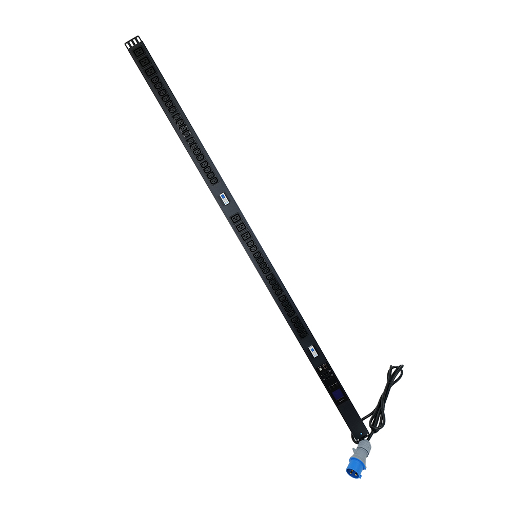
Because the two architectures have different chain length and vendor-mix profiles, so the data center that picks daisy-chain for a single-vendor, same-firmware row is the data center that saves the most per port; the data center that picks IP-share for a mixed-vendor, mixed-firmware row is the data center that protects the savings across the fleet’s natural refresh cycle. The wrong choice is the data center that picks daisy-chain for a mixed-firmware fleet and loses the cascade savings on the first firmware refresh.
3-Phase Cascading: The Phase-Balancing Trap
A 3-phase intelligent PDU cascades differently from a 1-phase PDU, and the difference is the phase-balancing requirement. A 1-phase chain can be connected in any order, with any combination of single-phase loads, and the per-phase current is the sum of the loads on the chain. A 3-phase chain has to balance the load across the three phases, with the chain’s total current draw on each phase within the PDU’s per-phase current limit. A network designer who cascades 3-phase PDUs without phase balancing is a network designer who has created a brownout risk on a single phase.
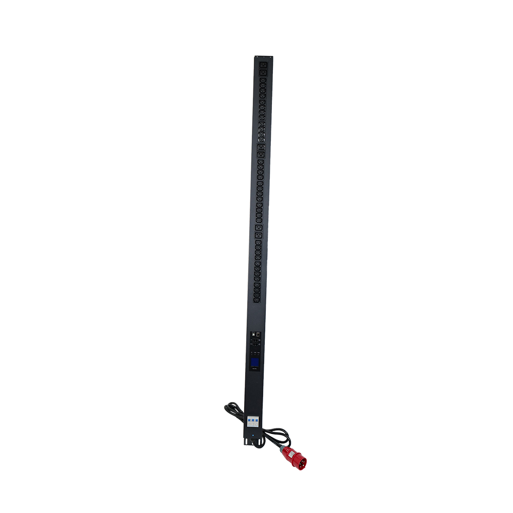
Three rules are the working default for 3-phase cascading. First, balance the load at the rack level. Each rack in the chain should draw roughly equal current on each phase, with a maximum 10–15% imbalance between phases. A rack that draws 20A on L1 and 8A on L3 is a rack that is creating a 12A imbalance, and a chain of 4 such racks is a chain that has a 48A imbalance across the phases. Second, balance the chain at the row level. The chain’s total current draw on L1, L2, and L3 should be within 5% of each other; a 5% imbalance is the threshold above which the neutral conductor starts to carry a non-trivial return current, and a 10% imbalance is the threshold above which the upstream breaker may nuisance-trip on a single phase. Third, monitor the per-phase current at the BMS. A cascade that does not report per-phase current to the BMS is a cascade that cannot detect a developing imbalance before it becomes a fault.
Port-Savings Math: The 35-Port Per Row Number
The port-savings math is the part of the cascade decision that closes the capex case to the CFO. The math is simple: count the number of PDUs in the row, divide by the cascade chain length, and the result is the number of switch ports the row needs. The savings is the difference between the PDU count and the chain count.
Row of 40 PDUs, cascade chain length 8:
  Without cascade: 40 switch ports
  With cascade:    ceil(40 / 8) = 5 switch ports
  Savings:         35 switch ports
  At a per-port capex of a low-three-figure USD (managed switch with 10-year amortisation):
  Savings per row: 35 ports * low-three-figure USD = mid-four-figure USD
  Across 10 rows:  350 ports * low-three-figure USD = mid-six-figure USD

Row of 8 PDUs, cascade chain length 8:
  Without cascade: 8 switch ports
  With cascade:    ceil(8 / 8) = 1 switch port
  Savings:         7 switch ports
  At a per-port capex of a low-three-figure USD:
  Savings per row: 7 ports * low-three-figure USD = mid-three-figure USD
  Across 10 rows:  70 ports * low-three-figure USD = low-five-figure USD
The math is the capex case, but the capex is not the only savings. The patch-panel real estate, the switch power and cooling, the switch management, the cable labour, and the documentation overhead all scale with the port count. A 35-port saving on a 40-rack row is a meaningful capex saving, a meaningful operations saving, and a meaningful documentation saving. The CFO sees the capex; the operations team sees the operations; the documentation team sees the documentation. The cascade decision is the right answer for all three stakeholders.
What Goes Wrong: Three Common Cascade Pitfalls
Three failure modes account for the majority of cascade-related service calls we see across our data center customers. None of them are catastrophic; all three are preventable with a documented design review before the install.
- Mixed-firmware cascade. A PDU on a chain running firmware version 2.4 and another PDU on the same chain running firmware version 3.0 is a cascade that does not cascade. The two PDUs recognise each other as different devices, the cascade falls back to individual IP polling, and the savings are lost. Prevention: specify the firmware version in writing on the purchase order, audit the firmware version on a sample of incoming PDUs with a documented process, and lock the firmware version across the chain in the BMS.
- Chain length beyond the spec. A cascade that is specified for 8 PDUs and installed with 12 is a cascade that is operating outside the spec. The cascade protocol typically fails silently at the 9th or 10th PDU, and the BMS reports a partial data set without flagging the gap. Prevention: specify the maximum chain length in writing, count the PDUs at the install, and audit the chain length at every firmware refresh.
- Phase imbalance on a 3-phase cascade. A 3-phase cascade that is installed with a 20% phase imbalance is a cascade that creates a neutral conductor return current of 20% of the chain’s total draw. The upstream breaker may nuisance-trip on a single phase, and the chain’s neutral conductor may be undersized for the return current. Prevention: calculate the per-phase current at the install, document the calculation in the commissioning report, and audit the per-phase current at every BMS review.
Procurement Checklist: Eight Questions to Ask the PDU Supplier
Eight questions, in order, that resolve the cascade spec for a data center intelligent PDU program. Answer them in writing, attach the answers to the supplier brief, and use them as the commissioning checklist on receipt.
- What cascade topology is supported? Daisy-chain only, IP-share only, or both? The supplier that supports only one is a supplier that has not specified for a multi-fleet data center.
- What is the maximum chain length? 4, 8, 16, or 32 PDUs per chain. The chain length is the gating constraint.
- What firmware version is required? All PDUs in the chain must run the same firmware. The firmware version has to be on the data sheet, not just on a verbal claim.
- What is the cascade cable? Vendor-specific RJ11 or RJ45, or standard Cat5e/Cat6 Ethernet. The cable type is the procurement variable.
- What is the per-phase current monitoring on a 3-phase PDU? Per-outlet current is the default; per-phase current is the right answer for a 3-phase cascade. The supplier that publishes per-phase data is the supplier that has specified for a cascade.
- What is the BMS protocol? Modbus TCP, SNMP, REST, or vendor-specific. The BMS protocol is the integration variable.
- What is the production lead time at the OEM’s MOQ? A custom OEM run is 30–45 days; a stock-SKU run is 10–20 days. A 90-day lead time is a sign the supplier is sourcing the PDU from a third party.
- What is the warranty? A 3-year warranty is the working default. A 1-year warranty is a sign the supplier is hedging on the firmware support cycle.
The eight questions above are the spec template any data center network designer should be running against every intelligent PDU quote. The supplier that answers all eight with a published data sheet, a firmware version list, and a BMS protocol list is the supplier that closes the deal. The supplier that cannot answer two of them is a trading company, and the data center is better off walking away before the rack is built.
Frequently Asked Questions
What is an intelligent PDU cascade?
An intelligent PDU cascade is a topology in which multiple PDUs share a single Ethernet management port and a single IP address, with the upstream PDU polling the downstream PDUs in series through a vendor-specific cascade protocol or a vendor-neutral gateway. The cascade is the working default for a data center row above 8 PDUs, with a 4–8 PDU daisy chain as the conservative case and an 8–32 PDU IP-share chain as the extended case.
What is the difference between daisy-chain and IP-share cascading?
A daisy-chain cascade is an in-band architecture in which each PDU has its own IP and the BMS polls the chain in series through a single port; the chain is single-vendor, single-firmware-version, and typically 4–8 PDUs long. An IP-share cascade is an out-of-band architecture in which a gateway device aggregates the chain and presents a single IP to the BMS; the chain is mixed-vendor, mixed-firmware-version, and typically 8–32 PDUs long.
What is the maximum chain length for a PDU cascade?
The working default is 4–8 PDUs for a daisy-chain and 8–32 PDUs for an IP-share. A chain beyond 8 PDUs on a daisy-chain typically fails the cascade protocol at the 9th or 10th PDU; an IP-share chain can go to 32 PDUs but the gateway polling time starts to dominate the BMS refresh cycle beyond 16–24 PDUs.
Can a 3-phase intelligent PDU cascade with a 1-phase intelligent PDU?
No. A 3-phase cascade has three phases that must be balanced across the chain; a 1-phase PDU has only one phase. The two topologies are not compatible on the same chain. A data center that has both 3-phase and 1-phase PDUs in the same row must run two separate chains, with the 3-phase chain on its own gateway and the 1-phase chain on its own gateway.
What switch-port savings does a cascade deliver?
A 40-rack row with 40 PDUs at one IP per PDU is 40 switch ports. The same row with 8-PDU daisy chains is 5 switch ports — a saving of 35 ports per row. Across a 10-row data center, the savings are 350 switch ports. The per-port capex varies by the switch model, but a managed switch amortisation is typically a low-three-figure USD line item per port over a 10-year life.
Does a cascade reduce the per-outlet monitoring granularity?
No. The cascaded PDUs still report per-outlet current, voltage, kWh, and switch state. The cascade reduces the network port count and the IP address count, not the data the BMS collects. A network designer who thinks the cascade reduces the per-outlet data is a network designer who has not read the PDU’s data sheet.
What is the cascade cable?
The cascade cable is the cable that connects the upstream PDU’s cascade-out port to the downstream PDU’s cascade-in port. For a daisy-chain, the cable is typically vendor-specific (RJ11 or RJ45). For an IP-share, the cable is typically a standard Cat5e or Cat6 Ethernet cable. The cable type is the procurement variable and has to be on the purchase order.
How do I verify a PDU supplier’s cascade claim?
Request three documents in writing: a published cascade architecture diagram, a firmware version list, and a BMS protocol list (Modbus TCP, SNMP, or REST). A supplier that has all three in 5–10 working days is a supplier that has the documentation practices that a data center program requires.
Where to Go From Here
If you are specifying a cascade topology for a data center intelligent PDU program, the next step is to share the eight-question procurement checklist above with the supplier and request a written response with the cascade architecture, the firmware version, and the BMS protocol. The intelligent PDU product line at Newsunn shows the daisy-chain and IP-share architectures supported by the program, with the firmware version list and the BMS protocol list. The OEM Swiss PDU supplier product page has the per-phase current monitoring spec and the cascade cable spec for the standard 1-phase and 3-phase PDU formats. For a custom cascade topology, a custom firmware version, or a custom BMS protocol, the Newsunn intelligent PDU solution team can quote a custom OEM run in 7–10 working days from a confirmed spec.
Send the eight-question procurement checklist to your shortlist and request a published cascade architecture diagram, a firmware version list, and a BMS protocol list. A serious supplier answers all eight in 7–10 working days; a trading company cannot answer three of them. The Newsunn intelligent PDU solution team is the entry point for the cascade topology conversation.
Post time: Oct-15-2026