

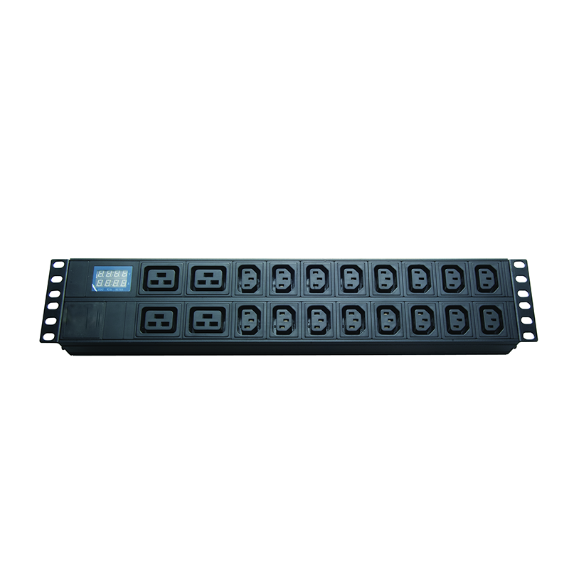
A 19″ 1U rack-mount PDU with IEC C13 and C19 outlets, rated at 16A per phase. This is the typical configuration used as the worked-example reference for the kW capacity calculations in this article.
Rack PDU kW Capacity Calculation: Formulas, Derating and Worked Examples
Sizing a rack PDU is the single most consequential decision in data center power distribution. Get the capacity too low and the breaker trips under load; get it too high and the rack operator is paying for copper and switchgear that is never used. For the OEM buyer evaluating a PDU product line for a hyperscale, colocation, or edge deployment, the question is not “what is the PDU’s nameplate kW” but “what is its usable continuous kW at the deployment’s ambient temperature, with the correct outlet mix for the loads being attached.”
This article walks through the four multipliers that drive every PDU capacity calculation, the three derating factors that compress the nameplate figure, and three worked examples that span the practical range from a 3.5 kW edge rack to a 45 kW full-load AI rack. The numerical examples are based on the Newsunn OEM 16A PDU reference configuration — the 19″ 1U rack-mount unit with C13 and C19 outlets and a C20 inlet described in the Newsunn PDU product portfolio and detailed on the OEM 16A power distribution unit product page.
1. The Three Variables That Drive Every PDU Capacity Calculation
Every PDU capacity calculation reduces to three electrical variables plus one configuration variable:
- V (Voltage): the line-to-line voltage for three-phase, or line-to-neutral voltage for single-phase. Typical values are 120V, 208V, 230V, 240V, 380V, 400V, 415V. The standard data center voltage in North America is 208V three-phase; in the EU/UK/CN it is 400V three-phase.
- I (Rated current): the maximum continuous current the PDU is designed to carry. Common ratings are 16A, 32A, 63A, and 100A per phase.
- PF (Power factor): the cosine of the phase angle between voltage and current. Server PSUs at full load typically run at PF 0.95–1.0; at 30% load PF can drop to 0.7–0.9. A conservative sizing uses PF = 0.95; an aggressive sizing uses PF = 1.0.
- Phase configuration: single-phase (one V × I pair) or three-phase (three V × I pairs summed via the √3 factor).
The voltage and current are stamped on the PDU’s nameplate and should be the starting point for any calculation. The power factor is rarely listed on the nameplate and must be estimated from the load profile. The phase configuration is determined by the building’s electrical service — single-phase 230V for most office and edge deployments, three-phase 400V for any data center above ~7 kW per rack.
2. The Core Formulas: Single-Phase, Three-Phase, and DC
The three core formulas for converting V × I × PF into kW are:
Three-phase: kW = (V × I × √3 × PF) / 1000
DC: kW = (V × I) / 1000 (no power factor in DC)
The √3 factor in the three-phase formula comes from the trigonometric relationship between the three phase voltages in a balanced three-phase system: when the three phases are 120° apart, the total instantaneous power is constant and equal to 3 × V_phase × I_phase × PF, which simplifies to V_line × I_line × √3 × PF. The √3 factor (~1.732) is what makes three-phase more efficient than single-phase at the same line current — three-phase delivers 73% more kW at the same line current.
The DC formula is included for completeness, but most rack PDUs operate on AC. The DC case applies to telecom -48V battery plants and to high-voltage DC (HVDC) data center deployments at 380V DC. The Newsunn OEM 16A PDU covered in this article is an AC unit; the DC formula would apply to the Newsunn DC power distribution panel portfolio.
| PDU Rating | Voltage | Phase | PF | Headline kW (full load) |
|---|---|---|---|---|
| 16A | 230V | 1φ | 0.95 | 3.50 kW |
| 32A | 230V | 1φ | 0.95 | 6.99 kW |
| 16A | 400V | 3φ | 0.95 | 10.53 kW |
| 32A | 400V | 3φ | 0.95 | 21.06 kW |
| 63A | 400V | 3φ | 0.95 | 41.46 kW |
| 32A | 415V | 3φ | 0.95 | 21.84 kW |
| 63A | 415V | 3φ | 0.95 | 43.05 kW |
These headline figures are the maximum nameplate kW the PDU can deliver under ideal conditions (25°C ambient, unity power factor correction at the load). The headline figures are the starting point for sizing — they are not the figure that should be used for breaker or PDU selection. The three derating factors below must be applied first.
3. NEC NFPA 70 80% Continuous-Load Derating
The first derating factor comes from the US National Electrical Code (NEC), also known as NFPA 70. Article 210.20(A) requires a branch circuit to be rated at no less than 125% of any non-continuous load plus 100% of the largest continuous load. Article 210.20(B) further clarifies that for circuits supplying continuous loads (defined as loads expected to operate for 3 hours or more), the overcurrent protection device rating must be at least 125% of the continuous load. The practical effect is that the maximum continuous load on a breaker is breaker_rating × 0.80 = 80% of the breaker rating.
In data center practice every load is treated as continuous because servers and network switches operate 24/7. This means a 32A breaker is practically a 25.6A continuous-load circuit, and a 16A breaker is a 12.8A continuous-load circuit. The PDU’s headline kW figure is reduced by 20% before it can be used for sizing.
The 80% rule is a US convention that has been broadly adopted in international data center design guides even where the local code is more permissive. European IEC 60364 and Chinese GB 50054 both have analogous requirements for continuous loads, though the exact percentage may differ. For a multi-region deployment, the 80% rule is the conservative default.
4. Outlet and Ambient Temperature Derating
The second derating factor comes from the IEC 60320 standard for appliance couplers. The C13/C14 inlet-outlet pair is rated 10A at 70°C pin temperature; the C19/C20 pair is rated 16A at 70°C pin temperature. The 70°C pin temperature is not the ambient temperature — it is the maximum temperature at the pin where it projects from the engagement surface, measured under full-load conditions. Above 70°C the connector body softens and contact resistance rises, creating a thermal runaway risk.
For a PDU with all C13 outlets, the practical per-outlet limit is 10A even if the PDU as a whole is rated 32A. For a PDU with all C19 outlets, the practical per-outlet limit is 16A. For a mixed PDU (which is the most common in server racks), the per-outlet limit depends on which outlet a particular load is plugged into. The total PDU kW capacity is not reduced by the outlet mix — the inlet and the internal wiring carry the full rating — but the per-device load must respect the outlet type.
The IEC 60309 three-phase industrial connectors used for higher-current PDU inlets (32A and 63A) have similar temperature constraints. The IEC 60309 standard uses different keying positions and diameters for 16A, 32A, and 63A three-phase connectors to prevent cross-connection — the 16A plug is physically smaller than the 32A socket and will not fit. This is a deliberate safety design that prevents over-current connections to under-rated outlets, per the Interpower connector reference and the Wikipedia summary of the IEC 60320 standard.
IEC 60320 outlet ratings: 10A, 16A, and the 70°C pin-temperature ceiling
The third derating factor is ambient temperature. Standard PDUs are rated for operation at 25°C ambient. As ambient rises, the internal bus bars, breaker thermal element, and outlet pin temperatures all rise in parallel. At some ambient the breaker thermal element trips before the full rated current is reached, because the bimetal thermal element’s trip curve shifts with temperature.
| Ambient Temperature | Typical Data Center Location | Capacity Multiplier |
|---|---|---|
| 25°C | Standard rating baseline | 1.00 (nameplate) |
| 30°C | Telco closet, edge cabinet | 0.95 |
| 35°C | Typical data center cold aisle setpoint | 0.90 |
| 40°C | Hot aisle cold-aisle mixed | 0.85 |
| 45°C | Hot aisle exhaust, worst-case | 0.80 |
| 50°C+ | Industrial, outdoor enclosure | 0.70 or breaker trip |
The ASHRAE TC 9.9 thermal guidelines for data centers recommend a cold-aisle intake temperature of 18–27°C (A1 class) for the most common server equipment, with allowance up to 32°C (A2 class) and 40°C (A3 class) for more tolerant equipment. At the A1 upper bound (27°C) the multiplier is essentially 1.00; at the A3 upper bound (40°C) the multiplier drops to 0.85. The ASHRAE A4 class allows up to 45°C with derated equipment — at this point the multiplier is 0.80 and the breaker trip risk becomes material.
For a rack-mount PDU mounted at the back of a high-density rack, the effective ambient is not the cold-aisle intake temperature but the hot-aisle exhaust at the rack rear door — which can reach 45°C at 15 kW per rack and compress capacity by 20%.
6. Worked Example 1: Single-Phase 230V, 16A PDU for a 3.5 kW Edge Rack
Step 2 (NEC 80%): 3.50 × 0.80 = 2.80 kW
Step 3 (IEC 60320 outlets): per C13 outlet ≤ 10A = 2.30 kW, per C19 outlet ≤ 16A = 3.68 kW — outlet mix not limiting for this load
Step 4 (ambient 25°C edge closet): 2.80 × 1.00 = 2.80 kW
For a small edge rack with two 1U servers, a top-of-rack switch, and a small storage array, the typical peak load is 2.5–3.0 kW. A 16A single-phase PDU delivers 2.8 kW of usable continuous capacity, which covers the load with about 7% headroom. This is the minimum practical PDU for any active edge deployment.
The decision rule for the edge rack buyer is: if the planned load is below 2.0 kW sustained, a 16A single-phase PDU is sufficient; if the planned load is 2.0–3.5 kW sustained, derate the figure and size to 3.5 kW peak; if the load is above 3.5 kW or expected to grow, move to a 32A single-phase or 16A three-phase PDU. The same calculation applies for the Newsunn PDU frequently asked questions page, which documents the same capacity range for the OEM 16A reference unit.
7. Worked Example 2: Three-Phase 400V, 32A PDU for a 22 kW Server Rack
Step 2 (NEC 80%): 21.06 × 0.80 = 16.85 kW
Step 3 (IEC 60320 outlets): per C13 ≤ 10A = 2.30 kW, per C19 ≤ 16A = 6.08 kW (3-phase 400V) — outlet mix not limiting
Step 4 (ambient 35°C cold aisle): 16.85 × 0.90 = 15.16 kW
A standard 42U server rack with 10 × 1U servers, 2 × 2U storage arrays, and a top-of-rack switch typically draws 8–12 kW. A 32A three-phase 400V PDU delivers 15.16 kW of usable continuous capacity in a typical cold-aisle data center — enough headroom for the load plus 30% growth without changing the PDU. This is the workhorse configuration for any mid-density data center deployment.
The three-phase 32A configuration also halves the per-phase cable copper content compared to delivering the same 15 kW on single-phase. For a retrofit or greenfield where cable tray space is constrained, three-phase 32A is the standard answer.
8. Worked Example 3: Three-Phase 415V, 63A PDU for a 45 kW Full-Load AI Rack
Step 2 (NEC 80%): 43.05 × 0.80 = 34.44 kW
Step 3 (IEC 60320 outlets): per C13 ≤ 10A = 2.41 kW, per C19 ≤ 16A = 6.27 kW (3-phase 415V) — outlet mix not limiting
Step 4 (ambient 45°C hot aisle): 34.44 × 0.80 = 27.55 kW
An AI rack with 8 × GPU servers (each ~5 kW nameplate), 2 × CPU servers, and 2 × high-speed InfiniBand switches typically draws 35–45 kW. A 63A three-phase 415V PDU delivers 27.55 kW at 45°C ambient — not enough for the high end. The AI rack deployment typically needs two 63A three-phase PDUs in a redundant A+B configuration, each delivering 27.55 kW to a half-loaded rack.
This is the configuration where ambient derating matters most. Liquid cooling at the rack rear door drops exhaust to 35–40°C, restoring the multiplier to 0.85–0.90 and adding 4 kW of usable capacity per PDU.
9. The Capacity Worksheet: How to Size a PDU in 7 Steps
The seven steps for sizing a rack PDU in the right configuration, from load enumeration to PDU selection, are:
- Enumerate the rack loads. List every server, switch, storage device, and PDU-fed device with nameplate wattage. If wattage is not on the nameplate, use the power supply rating (e.g. 2 × 1100W redundant PSU = 2200W peak).
- Apply the power factor. Server PSUs are typically PF 0.95–1.0 at full load, dropping to 0.7–0.9 at 30% load. Use PF = 0.95 for conservative sizing, PF = 0.90 for typical mixed-load sizing.
- Determine the phase configuration. Choose single-phase for edge racks below 5 kW; three-phase for any rack above 7 kW (3-phase cuts cable copper by 50% per kW delivered). Three-phase 400V is the EU/UK/CN standard; three-phase 208V is the North American standard.
- Apply the 80% continuous-load derating. Per NEC NFPA 70 210.20(A), multiply the target kW by 1.25 to get the minimum breaker rating, or multiply the breaker rating by 0.80 to get the maximum continuous load. Treat every data center circuit as continuous.
- Apply the ambient temperature derating. At 35°C cold aisle, multiply by 0.90. At 45°C hot aisle exhaust, multiply by 0.80. For mixed-location rack mounting, average to 0.85.
- Add growth headroom. Target 80% utilization for fixed-load deployments, 50% for growing deployments, 40% for AI/GPU deployments to absorb the next generation’s TDP increase without PDU replacement.
- Select outlet type and quantity. C13 outlets for devices under 10A; C19 outlets for devices between 10A and 16A. A mix of C13 and C19 is standard for most server racks.
The seven-step worksheet is essentially a checklist. For a real deployment the workbook takes about 30 minutes per rack — the time-consuming part is not the calculation but collecting the actual load wattage from each device’s nameplate or its iLO/iDRAC report.
10. Future-Proofing: What Headroom Do You Need for AI/GPU Load Growth?
The final variable in PDU sizing is future-proofing for the next GPU or CPU refresh. The historical per-server power trend has been a 25–30% increase per generation. A 10 kW rack today is likely a 15 kW rack in 3 years and a 20 kW rack in 5 years.
For an AI rack sized today, the practical question is: should the PDU deliver 40% or 80% utilization at today’s load? At 40% utilization (i.e. 60% headroom), the next-generation rack can absorb a 50% TDP increase without a PDU replacement. At 80% utilization, the next refresh needs a full PDU replacement — and potentially a larger upstream breaker and feeder cable.
| Deployment Type | Today’s Load | Today’s Utilization Target | 3-Year Headroom | 5-Year Headroom |
|---|---|---|---|---|
| Fixed (edge, telecom) | 2.8 kW | 80% | 25% | 40% |
| General IT (server rack) | 15 kW | 50% | 50% | 70% |
| AI/GPU (training) | 27 kW | 40% | 50% | 70% |
| AI/GPU (inference) | 12 kW | 50% | 50% | 70% |
The 40–50% utilization target for AI/GPU racks is a 2× cost on the PDU and upstream infrastructure compared to a 100% utilization design. The justification is that retrofitting a PDU, breaker, and feeder cable in an active data center costs 5–10x the incremental capital cost of sizing for future load. The economics favor over-sizing today.
FAQ
For single-phase: kW = V × I × PF / 1000. For three-phase: kW = V × I × √3 × PF / 1000. V is line-to-line voltage, I is the rated current per phase, PF is power factor (typically 0.9–1.0 for server loads, 0.95 is the conservative default).
NEC NFPA 70 Article 210.20(A) and 210.20(B) require branch circuits supplying continuous loads to be rated at no less than 125% of the continuous load. This means the maximum continuous load on a 30A circuit is 30 × 0.80 = 24A. The 80% rule is the practical derating factor for any circuit expected to carry load for more than 3 hours.
Per IEC 60320, the C13/C14 inlet-outlet pair is rated 10A at 70°C pin temperature; the C19/C20 pair is rated 16A at 70°C pin temperature. C13 is the standard connector for computers, monitors, and general IT equipment; C19 is used for higher-power IT equipment, data center PDUs, and kilowatt-class power supplies.
Standard PDUs are rated for operation at 25°C ambient. At 35°C ambient (typical data center cold aisle setpoint), expect roughly 90% of nameplate capacity. At 45°C (worst-case hot aisle exhaust), expect 80%. Above 50°C the breaker may trip before the full rated current is reached, because the bimetal thermal element’s trip curve shifts with temperature.
For a fixed-load deployment, plan for 80% nameplate utilization at full load to leave the NEC-mandated 20% headroom. For a growing deployment, plan for 50% utilization at full load with the next-generation PDU’s higher amperage available. For AI/GPU racks whose load is increasing per generation, plan for 40% utilization on the current generation so the next GPU refresh does not require a full PDU replacement.
A 16A PDU uses an IEC 60320 C20 inlet on single-phase or a smaller industrial plug on three-phase; a 32A PDU uses an IEC 60309 32A three-phase industrial connector. On single-phase 230V, the 16A PDU delivers 3.7 kW (full) and the 32A PDU delivers 7.4 kW. On three-phase 400V, the 16A PDU delivers 11 kW and the 32A PDU delivers 22 kW.
No. The IEC 60309 standard uses different keying positions and diameters for 16A and 32A three-phase connectors to prevent cross-connection. The 16A plug is physically smaller than the 32A socket and will not fit. This is a deliberate safety design that prevents over-current connections to under-rated outlets.
External References
The NEC NFPA 70 80% continuous-load derating rule and its application to equipment rack internal wiring are documented in the Industrial Monitor Direct reference for equipment rack wiring, which applies Article 210.20(A) and 210.20(B) to the derating of branch circuits supplying continuous loads[1]. The IEC 60320 connector ratings (C13 10A, C15 10A or 16A at 120°C, C19 16A, all at 70°C pin temperature) are catalogued in the IEC 60320 Wikipedia reference and the Interpower connector reference[2][3]. The C13 vs C19 current and power capacity comparison (10A/2500W vs 16A/4000W) is provided by the Focc-fiber power cord reference[4]. The Raritan iPDU Handbook provides the data center industry reference for rack PDU sizing, including the 70% nameplate-to-actual derating rule and the 80% continuous-load rule applied in this article[5].
References cited in this article:
[1] Industrial Monitor Direct: NEC Code Derating Rules for Equipment Rack Internal Wiring
[2] Wikipedia: IEC 60320
[3] Interpower: More Information on IEC 60320 C13 Connectors
[4] Focc-fiber: C13 vs. C19 Power Cord Comparison
[5] Raritan: The iPDU Handbook (PDF)
Product references: PDU capacity options · 16A power distribution unit · Power rating questions answered
Post time: Aug-12-2026